Aluminum Electrolytic Capacitor Design for Automotive use
January 18, 2018
Introduction
n recent years, the number of electronic control units (ECUs) mounted within a vehicle has increased incrementally with the progression of automotive electrification. The requirements for capacitors used are small, lightweight and can withstand high voltage, vibration, temperature and current while achieving low resistance (low ESR) to optimize temperature rise. In response to these various requirements, Rubycon has created capacitors for automotive applications by utilizing the use of design and simulation technologies as shown in Fig. 1.
Our goal to our customers is to propose automotive designs that contribute to cost reduction, miniaturization and high performance, while the ECU market is steadily increasing in demand and content.
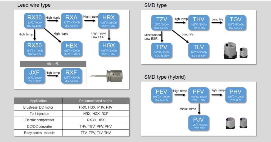
Below, we have introduced several series and design techniques that are ideal for automotive applications.
Aluminum electrolytic capacitors for automotive applications
The features of three major products (Table 1) out of a variety of our capacitors for automotive use are introduced below.
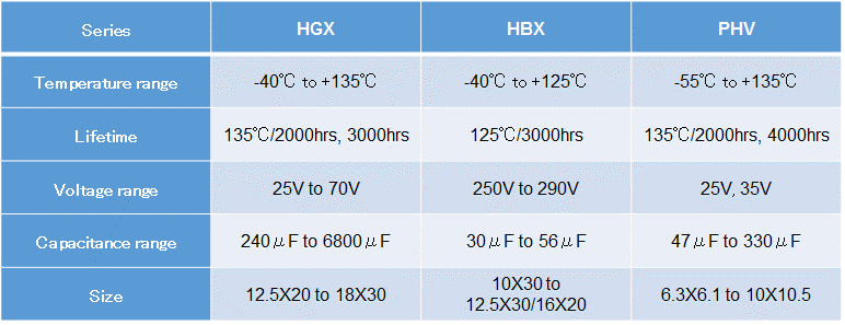
Suitable for AEC-Q 200 which is one of the reliability test standards for automotive electronic parts.
“HGX series”
HGX series is a product developed for low voltage DC link inverter circuits. They specialize in high heat resistance, ripple current and capacitance. It is particularly suitable for brushless DC motor control unit such as electric power steering (EPS), engine cooling fan and fuel injection control units. This series dramatically improves the durability against ambient temperature and self-heat generation by adopting a newly developed high heat-stable / low resistance electrolyte along with heat resistant sealing rubber. It realizes high ripple current at the upper category temperature of 135ºC and permissible operating temperature up to 150ºC. In addition, it has the versatility of size customization with increments of 1 mm allowing it to fit into tight mounting space within the vehicle from the use of our own high-performance production lines which are dedicated to automotive capacitors.
“HBX series”
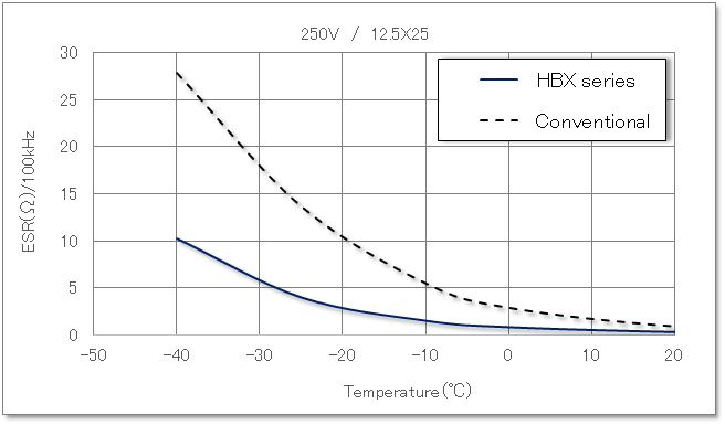
The HBX series is a product developed for DC link of high voltage inverter drives specializing in high heat resistance and ripple current with a rated voltage of 250 to 290 Volts DC. It has top performance in terms of low temperature characteristics and heat resistance. This series has a high market share in the electric compressor market for automotive air conditioners, and further demand expansion is expected with the growing market of electric and plug in hybrid vehicles. Electric compressors are required to operate under high stress and high temperature conditions with the ability to thrive in extremely cold regions. For this reason, the HBX series offers the highest level of ripple current at the upper category temperature of 125ºC and far lower ESR at -40ºC than other conventional products. This is achieved through the adoption of a special electrolyte that has been designed for a high heat resistance along with low temperature performance. This in combination with a low resistance separator paper are what is used to achieve such high performance. (Fig. 2)
“PHV series”
The PHV series is a surface mount conductive polymer aluminum electrolytic capacitor (hybrid type) which uses a conductive polymer as the electrolyte and adds a unique functional liquid in lieu of traditional wet type electrolyte. This solid construction offers many unique advantages such as life and temperature performance vs. competitive types which utilize a wet type electrolyte with their polymer. The upper category temperature of this series is 135ºC. The PHV series has stable frequency characteristics over a wide temperature range and features low ESR variance vs. temperature. If you derate the temperature to 125ºC, the PHV series allows the rated ripple current for roughly twice that of our conventional hybrid type “PFV series.”
The PHV series with high heat resistance and ripple current has the potential to downsize any ECU such as DCDC converter and brushless DC motors.
Design techniques for optimizing capacitors
Thermal Design
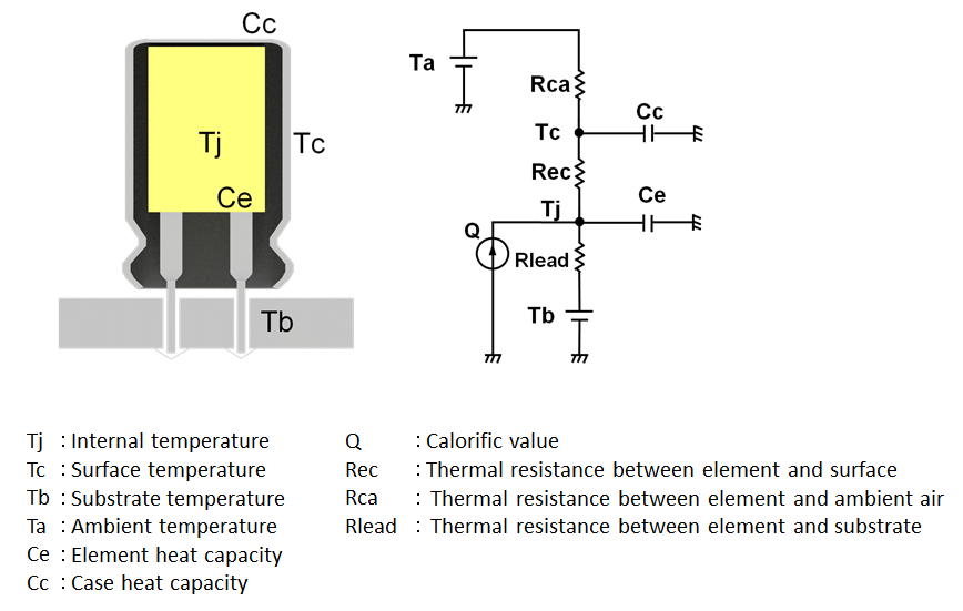
The life of an aluminum electrolytic capacitor is primarily defined by the ambient temperature and self-heating due to the applied ripple current. To properly estimate life, an accurate measurement of the internal temperature is especially important for under hood and powertrain applications where high temperature and ripple are common. We have conducted extensive thermal conductivity analysis of each capacitor by utilizing a finite element method. We then create an accurate thermal equivalent circuit model (Fig. 3) by comparing and adjusting it with experimental data. It becomes possible to estimate the internal temperature of the capacitor assuming the actual use environment by incorporating the mounting conditions (thermal parameter) presented by the customer into this thermal equivalent circuit model. It becomes possible to prevent overheating of the capacitor and avoid excessive design through this method. As a result, this process contributes to downsizing, weight and cost reduction through proper capacitor selection.
Short-term High Current
Capacitors for automotive ECUs such as electric power steering and fuel injection applications are often required to cope with short-term high current. This typically exceeds the rated ripple current specification of the capacitor. In this case, not only the peak current value but also current duty ratio is key to estimate the heat generation due to the ripple current. This is because the actual temperature inside the capacitor largely depends on the current duty ratio. The difference in the actual internal temperature of the capacitor caused by the difference in current duty ratio is shown in Fig. 4.
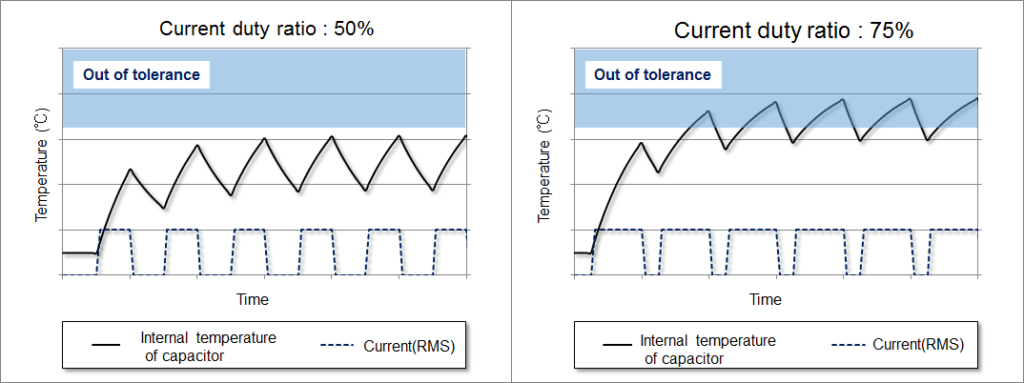
The internal temperature (due to the heat generation of the capacitor) must be lower than the max permissible upper temperature limit of the capacitor. If the temperature exceeds the maximum limit, then there is a risk of short circuit due to dielectric breakdown between the electrodes. The capacitor vent may open due to the rise in the internal pressure from the gas generation. Since the ESR value increases over time due to heat generation, the estimation of the internal temperature should also consider the ESR value increase due to deterioration of the capacitor. Therefore, we can simulate the internal temperature by knowing the permissible upper limit temperature of the capacitor and the change in ESR level with time. We are then able to design a capacitor with the ability to tolerate short-term high current.
Vibration Proof
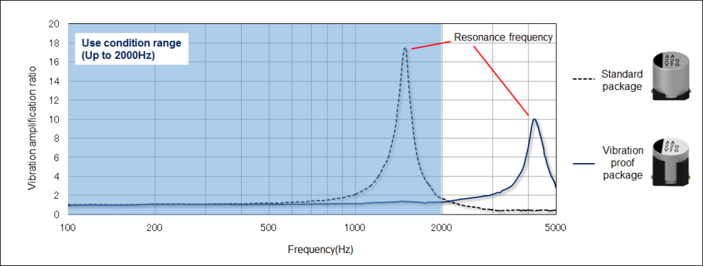
Capacitors for automotive use are required to survive vibrations in excess of 20 G peak amplitude due to the mounting on or near engine and the advancement of mechatronics integration. However, since the resonance frequency of a surface mount capacitor with a standard structure exists within the vibration frequency range (about 5 Hz to 2000 Hz) used for automotive device unit, the capacitor will fail by amplified vibration amplitude at the resonance frequency. Therefore, it is important to bring the resonance frequency of the capacitor beyond the range of the use conditions. Figure 5 shows the frequency characteristics comparison of the vibration amplification ratio of the vibration proof package with the standard package. The resonance frequency of the vibration proof package shifts from 1500 Hz of the standard package to 4200 Hz, and the vibration amplification ratio of the vibration proof package can be suppressed to 2.0 or less within the supposed frequency range. Package improvements have made for remarkable progress on vibration resistance with performance up to 30 G or more.
Load Dump Surge
Transient voltage is temporarily applied to the input capacitor in load dump surge assuming abnormal situation such as battery disconnection during engine operation. Since transient voltage causes insulation breakdown of the capacitor and causes short circuit, appropriate materials satisfying the required condition (voltage, application time, ambient temperature) are selected, considering the withstand voltage and temperature dependency of the anode foil, separator and electrolytic solution which constitute the capacitor.
In-rush Current
Since inrush current with several hundreds of peak amps can flow at the instant the ECU is connected to the battery, robustness against inrush current is required for the capacitor. The robustness depends on current durability of the connecting portion between the lead wire terminal and the electrode foil of the capacitor. This connection point operates in a similar fashion to a single use fuse. In the case of peak current value being too high, a spark may occur at the junction to short-circuit. We change the connection specifications according to the magnitude of the peak value and the number of cycles. We then design a capacitor that meets such conditions.
As described above, when designing a capacitor for automotive use, it is necessary to understand various usage environments and conditions for each application, and correctly reflect the information in development and design of the capacitor.
In addition, we offer a 3D CAD, and spice modeling (15 elements) along with a lifetime calculation tool. Such design tools will help to support proper design of the capacitor while shortening the design cycle.
Future Prospects
From the standpoint of environmental protection, the latest movement of electrification with Electric Vehicle and Plug-in hybrids has accelerated globally in the automobile industry. In addition, the advancement of ADAS (Advanced Driving Assistance System) technology is realizing full autonomous driving. The Infrastructure market for charging and information communication is expected to grow in the future, and efforts toward product development for the entire mobility system has become increasingly important.
We will continue to further promote the design, material and manufacturing of advanced technologies, and will promptly provide high-performance products to the market that respond to increasingly sophisticated and complicated market requirements.
*This article was published in the column”High technology” on the Dempa Shimbun Daily dated on Jan. 18, 2018