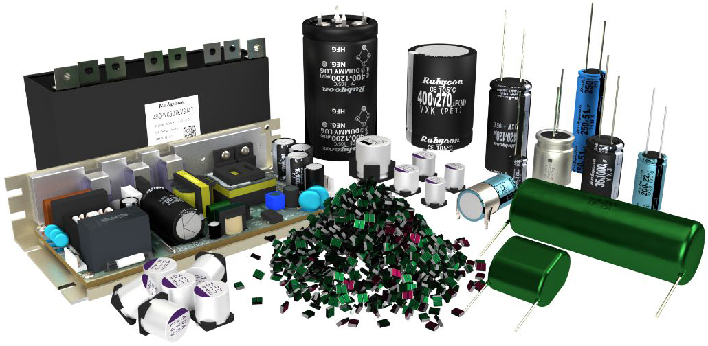
Radial lead Aluminum Electrolytic Capacitors
- Features
- Series List / Series Chart
- Design Support
- Documents
- FAQ
Rubycon is one of the design and manufacturing pioneers for aluminum electrolytic capacitors. Its core products set the standard for performance and reliability. Rubycon will continue to take on the challenges to push the envelop in performance and volumetric efficiency.
An aluminum electrolytic capacitor is used in various types of electronic equipment. It is a low-cost component that is critical to the reliable performance of your electronic devices.
Rubycon will continue to take on the challenge of improving our technology to be the benchmark for our industry.
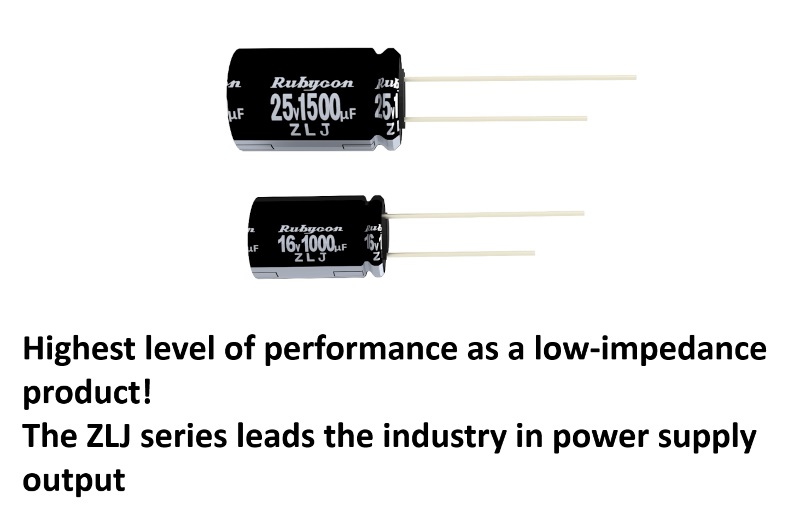
Leading the industry with low impedance products
Aluminum electrolytic capacitors are inexpensive and offer high capacitance, but they have the disadvantage of high internal resistance.
Rubycon has developed the industry’s first water-based electrolyte using our original electrolyte blending technology, and has developed the industry’s highest performance low impedance product. This electrolyte dramatically reduces the resistance of the capacitor, greatly contributing to the high performance of the power supply.
In addition to aqueous electrolytes, we also have a lineup of low-impedance products that use high-performance electrolytes.
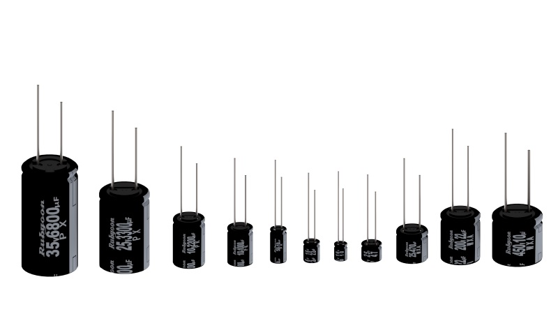
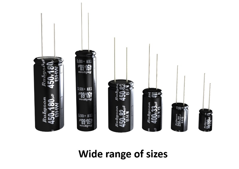
Wide range of sizes
The size of aluminum electrolytic capacitors for power input have a great impact on the miniaturization of equipment. Rubycon has been using delicate materials which were considered to be difficult to commercialize through the development of our own processes, and has developed miniaturized capacitors, low-profile products, and long, thin pencil type capacitors for power input.
We are contributing to the miniaturization of equipment with these abundant size variations.
High quality product lineup
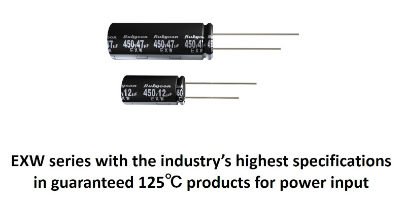
The operating environment for electronic devices, including in-vehicle electrical equipment, is becoming more and more severe. Rubycon has been offering products with the highest specifications in the industry, such as high temperature guaranteed products and long life products, based on our unique development capabilities.
In recent years, long life products and high temperature guaranteed products using the latest technology are increasingly being used in automotive chargers and power supplies for communication base stations.
Products that are friendly to the global environment
Rubycon is committed to the reduction of environmentally hazardous substances on an international scale, and develops, produces, and sells earth-friendly products that comply with laws and regulations.
We deliver products that are compliant with the EU RoHS Directive (2011/65/EU) and its amendments (2015/863/EU).

Animation of the manufacturing process
Series List
Lead Wire Type Aluminum Electrolytic Capacitors
| Type | Series | Details | Search | Features | General purpose | Miniaturized | High Temp | High Ripple | Long life | Low Z Low ESR | AEC-Q200 | Rated voltage(Vdc) | Capacitance(μF) | Category Temperature Range | Series |
|---|---|---|---|---|---|---|---|---|---|---|---|---|---|---|---|
| General Purpose | PK ※1 |
|
|
85℃ Standard |
◯ | ◯ | 6.3~400 450 |
0.47~33,000 0.47~100 |
-40~+85 -25~+85 |
PK ※1 | |||||
| PX ※1 |
|
|
105℃ Standard |
◯ | ◯ | 6.3~100 160~400 450 |
1~33,000 0.47~100 1~100 |
-55~+105 -40~+105 -25~+105 |
PX ※1 | ||||||
| Miniaturized/Low Profile | WXA |
|
|
105℃ 9mm~25mm Height |
◯ | ◯ | 6.3~50 160~250 350~450 |
100~10,000 4.7~220 1.5~68 |
-55~+105 -40~+105 -25~+105 |
WXA | |||||
| ML |
|
|
105℃ 9mm Height |
◯ | ◯ | 6.3~50 | 82~1,000 | -40~+105 | ML | ||||||
| Low Impedance | YXS |
|
|
105℃ Low Impedance |
◯ | ◯ | ◯ | 6.3~50 | 22~22,000 | -40~+105 | YXS | ||||
| YXJ ※1 |
|
|
105℃ Long Life |
◯ | ◯ | ◯ | ◯ | 6.3~100 | 1~22,000 | -40~+105 | YXJ ※1 | ||||
| ZLS |
|
|
105℃ Miniaturized, |
◯ | ◯ | ◯ | 10~35 | 220~5,600 | -40~+105 | ZLS | |||||
| ZLH |
|
|
105℃ Miniaturized, Long Life, |
◯ | ◯ | ◯ | ◯ | 6.3~100 | 8.2~8,200 | -40~+105 | ZLH | ||||
| ZLJ |
|
|
105℃ High Ripple Current, Long Life, |
◯ | ◯ | ◯ | ◯ | 6.3~120 | 8.2~8,200 | -40~+105 | ZLJ | ||||
| ZLQ |
|
|
105℃ Ultra Miniaturized, |
◯ | ◯ | ◯ | 6.3~35 | 56~12,000 | -40~+105 | ZLQ | |||||
| new ZLR |
|
|
105℃ Miniaturized, Long Life, |
◯ | ◯ | ◯ | ◯ | 16~35 | 56~5,600 | -40~+105 | new ZLR | ||||
| JXF |
|
|
105℃ Low Impedance, |
◯ | ◯ | ◯ | ◯ | ◯ | 16~100 | 68~10,000 | -55~+105 | JXF | |||
| ZLG |
|
|
105℃ Ultra Low Impedance |
◯ | ◯ | 6.3~35 | 33~3,900 | -40~+105 | ZLG | ||||||
| YXF ※2 |
|
|
105℃ Long Life |
◯ | ◯ | ◯ | 6.3~50 | 1~15,000 | -40~+105 | YXF ※2 | |||||
| YXG ※2 |
|
|
105℃ Low Impedance |
◯ | ◯ | ◯ | 6.3~100 | 6.8~18,000 | -40~+105 | YXG ※2 | |||||
| YXH ※2 |
|
|
105℃ Long Life, |
◯ | ◯ | ◯ | 6.3~50 (63~100) |
6.8~18,000 | -40~+105 | YXH ※2 | |||||
| ZL ※2 |
|
|
105℃ High Ripple, |
◯ | ◯ | 6.3~50 (63~100) |
22~6,800 | -40~+105 | ZL ※2 | ||||||
| ZLK ※2 |
|
|
105℃ Ultra High Ripple Current, |
◯ | ◯ | 10~35 | 220~1,800 | -40~+105 | ZLK ※2 | ||||||
| Long Life | CFX |
|
|
105℃ 5,000hours |
◯ | ◯ | 200~400 | 2.2~100 | -25~+105 | CFX | |||||
| BXC |
|
|
105℃ 8,000~12,000hours |
◯ | 160~500 | 1~220 | -25~+105 | BXC | |||||||
| BXG |
|
|
105℃ 10,000~12,000hours, |
◯ | ◯ | 160~450 | 8.2~270 | -40~+105 | BXG | ||||||
| LLE |
|
|
105℃ 12,000~20,000hours |
◯ | ◯ | 160~400 450 |
1~33 4.7~68 |
-40~+105 -25~+105 |
LLE | ||||||
| LEX |
|
|
125℃ 3,000~5,000hours |
◯ | ◯ | ◯ | 160~450 | 1~33 | -40~+125 | LEX | |||||
| YXM |
|
|
105℃ 10,000hours, |
◯ | ◯ | 10~100 | 1~330 | -40~+105 | YXM | ||||||
| TXW |
|
|
105℃ 7,000~10,000hours |
◯ | ◯ | ◯ | 35~100 | 100~1,800 | -40~+105 | TXW | |||||
| High Temperature | RX30 ※1 |
|
|
130℃ 1,000~4,000hours |
◯ | ◯ | ◯ | 10~100 200~400 |
4.7~4,700 1~33 |
-40~+130 -25~+130 |
RX30 ※1 | ||||
| RXA |
|
|
125℃ 2,000~3,000hours |
◯ | ◯ | ◯ | ◯ | ◯ | 25~70 | 240~5,600 |
-40~+125 |
RXA | |||
| RXF |
|
|
125℃ 2,000~5,000hours, |
◯ | ◯ | ◯ | ◯ | ◯ | 25~80 | 180~7,500 | -55~+125 | RXF | |||
| RXG |
|
|
150℃ 1,500hours |
◯ | ◯ | ◯ | 10~63 | 47~3,600 | -40~+150 | RXG | |||||
| RXL |
|
|
125℃ 3,000~8,000hours, |
◯ | ◯ | ◯ | ◯ | ◯ | 16~35 | 510~7,500 | -55~+125 | RXL | |||
| RX50 ※2 |
|
|
150℃ 1,000hours |
◯ | ◯ | ◯ | 10~63 | 47~1,000 | -40~+150 | RX50 ※2 | |||||
| HRX |
|
|
125℃ 2,000~3,000hours |
◯ | ◯ | ◯ | ◯ | 25~70 | 240~5,100 | -40~+135 | HRX | ||||
| HGX |
|
|
135℃ 3,000hours |
◯ | ◯ | ◯ | ◯ | 25~70 | 240~6,800 | -40~+135 | HGX | ||||
| HBX |
|
|
125℃ 2,000~3,000hours, |
◯ | ◯ | ◯ | ◯ | 250~290 | 24~56 | -40~+125 | HBX | ||||
| HCX |
|
|
125℃ 3,000hours, |
◯ | ◯ | ◯ | ◯ | 250~290 | 22~51 | -40~+125 | HCX | ||||
| Miniaturized For Power Supply | QXW |
|
|
105℃ 2,000hours, |
◯ | ◯ | 200~450 | 12~560 | -40~+105 | QXW | |||||
| HXW |
|
|
105℃ 2,000~3,000hours, |
◯ | ◯ | 400~500 | 22~270 | -40~+105 | HXW | ||||||
| new AEW |
|
|
105℃ 2,000~3,000hours, |
◯ | ◯ | 400~450 | 82~300 | -40~+105 | new AEW | ||||||
| CXW |
|
|
105℃ 5,000hours |
◯ | ◯ | ◯ | 180~450 | 10~680 | -40~+105 | CXW | |||||
| BXW |
|
|
105℃ 10,000~12,000hours, |
◯ | ◯ | ◯ | ◯ | ◯ | 160~450 | 10~820 | -40~+105 | BXW | |||
| LXW |
|
|
105℃ 10,000~12,000hours, |
◯ | ◯ | ◯ | ◯ | 400~500 | 18~220 | -40~+105 | LXW | ||||
| new LEW |
|
|
105℃ 12,000hours, |
◯ | ◯ | ◯ | 400~450 | 82~270 | -40~+105 | new LEW | |||||
| EXW |
|
|
125℃ 3,000~5,000hours |
◯ | ◯ | ◯ | ◯ | 400~450 500 |
12~150 8.2~82 |
-40~+125 -25~+125 |
EXW | ||||
| BHW |
|
|
105℃ 10,000~12,000hours, |
◯ | ◯ | ◯ | ◯ | 400~450 | 47~220 | -40~+105 | BHW | ||||
| AX |
|
|
105℃ 2,000hours |
◯ | ◯ | 6.3~35 400 |
180~1,200 4.7~24 |
-40~+105 -40~+105 |
AX | ||||||
| KXW ※2 |
|
|
105℃ 2,000hours |
◯ | ◯ | 200~450 | 18~560 | -25~+105 | KXW ※2 | ||||||
| SAW |
|
|
105℃ Over-Voltage Venting Specification, |
◯ | ◯ | 200~450 | 4.7~270 | -25~+105 | SAW | ||||||
| SBW |
|
|
105℃ Over-Voltage Venting Specification, |
◯ | ◯ | 400 | 18~100 | -25~+105 | SBW | ||||||
| SXW ※2 |
|
|
105℃ Over-Voltage Venting Specification |
◯ | 200~400 | 4.7~330 | -25~+105 | SXW ※2 | |||||||
| For Special use | TWL ※1 |
|
|
85℃ Low Leakage Current |
◯ | 6.3~50 | 1~2,200 | -40~+85 | TWL ※1 | ||||||
| NXA ※1 |
|
|
105℃ Bi-Polar |
◯ | 6.3~50 | 1~1,000 | -40~+105 | NXA ※1 |
*1:Some values are scheduled to be discontinued. Please check the "Details" for each series.
*2:Products have been discontinued. Please avoid adopting for new projects.
Series Chart
Technical Note

Catalog
Product Specifications
1.Part Number (43 KB)
2.Packing Quantity (33 KB)
Cautions for Proper Use
Environmental Information
FAQ
What consequences are expected when the voltage exceeding the rated voltage is applied on an aluminum electrolytic capacitor?
On the anode foil of aluminum electrolytic capacitor, an oxide film capable of withstanding the rated voltage even if it is continuously applied at the maximum operating temperature.
In case when the voltage higher than the withstand voltage of this oxide film (overvoltage) is applied, the anode foil of aluminum electrolytic capacitor will form the oxide film equivalent to the applied voltage. Owing to the reaction, gases will be generated, thus leading to the pressure buildup in the capacitor. As the characteristics of capacitor, decrease in electrostatic capacity and increase in tangent of loss angle will be caused. The higher the applied voltage is and the higher the ambient temperature is, the more the gases are generated and the higher the internal pressure. This may sometimes lead to the phenomena such as swelling of sealing material (rubber packing) and further to activation of safety device (slipping out of rubber packing in the products with no safety device). Therefore, avoid the use of capacitor in the circuit where the voltage exceeding the rated voltage may be applied to it.
The structural breakdown modes in case when overvoltage is applied are as follows:
(1) Open
The safety device is activated (or rubber packing slips out), and liquid electrolyte in the capacitor is flown out, thus leading to dryup and finally to open condition.
(2) Short-circuiting
If the voltage higher than the withstand voltage of anode foil, that of liquid electrolyte and that of separator paper is applied and it is no longer possible to keep insulation, dielectric breakdown will be caused, thus leading to short-circuiting.
What consequences are expected when the voltage of reverse polarity is applied on an aluminum electrolytic capacitor?
The anode foil of polar aluminum electrolytic capacitor is subjected to chemical conversion treatment forcedly so as to have withstand voltage corresponding to the rated voltage of capacitor, while a cathode foil has substantially no withstand voltage because it is not subjected to such chemical conversion treatment. However, since aluminum is an active metal, it may react with oxygen in the air to form oxide film naturally on the cathode foil. Owing to this film, it is said that the cathode foil will have the withstand voltage of about 1 to 1.5 V at room temperature. Since this film is not uniform, but unstable, and shows dispersion partly or for each lot, no guarantee is given to the withstand voltage of cathode. In the circuit in which polarity is reversed, it is recommended to use a non-polarized aluminum electrolytic capacitor.
In case when the voltage higher than the withstand voltage is applied on the cathode foil of polar aluminum electrolytic capacitor, a current flows to electrolyze the water content in the liquid electrolyte. Then, oxygen generated by such electrolysis will react with the cathode foil to form oxide film on the cathode foil surface (chemical conversion coating of cathode foil). Owing to this reaction, the cathode foil capacity will lower. Since the capacitor capacity is the combination of anode and cathode foil capacities, this may lead to the decreased capacity of capacitor and further to the increase in tangent of loss angle (tan δ).
Moreover, owing to this reaction, gases will be generated in the capacitor, thus leading to the internal pressure buildup. The higher the applied voltage is and the higher the ambient temperature is, the more the gases are generated. Depending on the applied voltage and temperature, this may sometimes lead to the phenomena such as swelling of rubber packing of the capacitor and sometimes to activation of safety device or slipping out of rubber packing in the products with no safety device. Therefore, avoid the use of capacitor in the circuit where reverse polarity connection of capacitor or application of reverse voltage may occur.
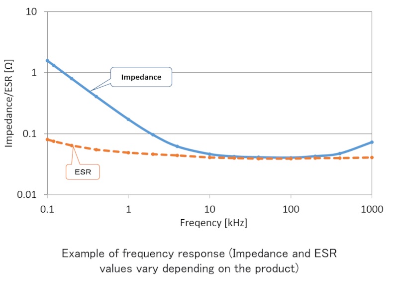
Is there any frequency dependence in aluminum electrolytic capacitors?
Each characteristic of an aluminum electrolytic capacitor has a frequency dependency.
The figure on the below shows a graph of typical frequency characteristics of impedance and ESR. Impedance decreases up to the resonance point and increases above the resonance frequency. This change is due to the nature of the aluminum oxide film as the dielectric, the characteristics of the electrolyte, and the structure of the capacitor. Since this characteristic value varies depending on the series and capacitance, it is necessary to confirm that there is no problem in the circuit operation by checking the operation with the actual capacitor to be used.
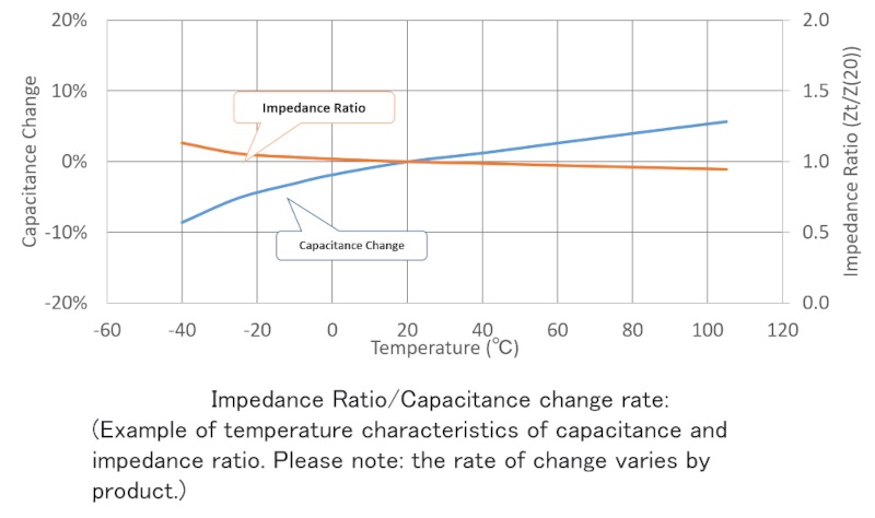
Is there any temperature dependency in aluminum electrolytic capacitors?
The characteristics of a capacitor are not constant even within the specified temperature range. The figure on the below shows an example of the temperature variation of capacitance and impedance. Due to the characteristics of the electrolyte, the capacitance of an aluminum electrolytic capacitor increases and the impedance decreases at high temperatures. At lower temperatures, the capacitance decreases and the impedance increases. Since these characteristic values vary depending on the series and capacitance, it is necessary to confirm that there is no problem in the circuit operation by checking the operation on the actual device using the capacitor to be used.
Also, if the capacitor is used above the upper limit of the category temperature, the pressure inside the capacitor will increase due to the rise in vapor pressure of the electrolyte and the electrochemical reaction caused by the current flow, which can result in rupture or leakage.
What are the failure modes of aluminum electrolytic capacitors?
In aluminum electrolytic capacitors, electrolyte is injected inside the capacitor, and the sealing material is tightened with the aluminum case to maintain a seal. However, as the electrolyte evaporates through the molecules of the sealing material, the amount of electrolyte inside decreases over time. As a result, the capacitance of the capacitor decreases and the resistance increases, eventually leading to an open circuit failure. However, the failure mode may vary depending on the usage conditions, such as when the environmental conditions or board mounting conditions exceed the specifications of each product.
Please refer to the catalog and technical notes for typical failure modes and their causes.
Is it possible to estimate the life expectancy of aluminum electrolytic capacitors in actual use?
The life of an aluminum electrolytic capacitor is highly temperature dependent, and can be estimated based on the environmental temperature at which the capacitor is actually used, the temperature of the capacitor, and the self-heating temperature of the capacitor.
To estimate the service life, we use the service life estimation formula based on accelerated test data. Please refer to the “Life expectancy” section of the Technical Note, as it varies depending on the capacitor shape and series. Please note that the results of this formula are not guaranteed and should be treated as reference values.
Is it safe to use aluminum electrolytic capacitors in high altitude?
When aluminum electrolytic capacitors are used in equipment that will be used at high altitudes, such as in the mountains or in airplanes, it is assumed that the pressure inside the capacitor will increase due to a decrease in external air pressure. However, there is no problem in the sealing performance of the capacitor when used in the atmosphere at an altitude of about 10,000m. However, as the temperature drops as the altitude increases, please take into account the temperature dependency of the characteristics of aluminum electrolytic capacitors when checking the operation of the equipment.
Is it safe to use aluminum electrolytic capacitors that have been stored for a long time?
When aluminum electrolytic capacitors are stored for a long period of time, the oxidation of the lead wire surface may affect the solderability and the increase in leakage current may cause circuit malfunction. In addition, the characteristics will deteriorate even if the capacitor is not in use.
Even if the product has been stored for a long period of time, the leakage current can be reduced to the initial level by implementing voltage treatment, so it is possible to prevent malfunctions due to the effects of leakage current. However, other characteristics that have deteriorated during the storage period will not return to their original state, so consider the expected lifetime of the set, storage period, and storage conditions when using long-term stored products. For precautions on storage conditions, please refer to the Precautions for Use.