Film Capacitors
- Features
- Series List / Series Chart
- Design Support
- Documents
- FAQ
Animation of the manufacturing process
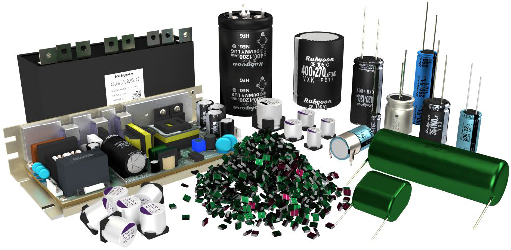
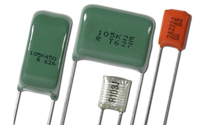
Low loss and high insulation characteristics
Film capacitors use plastic film as the dielectric material which have low loss and high insulation characteristics.
Rubycon’s film capacitors are ideal for high-frequency electronic equipment achieving high temperature/humidity resistance from our unique technology. They are widely used in inverter, switching power supply circuits of audio-visual (AV) equipment, information, communication, RF, lighting as well as automotive equipment in harsh operating environments.
High Current
The high current series, which achieves low ESR by increasing the area of internally connected electrodes, achieves an increase in allowable current of about 30% in the same volume.
High heat resistance
We have newly released the MPT series, which is compatible with 125℃, as a high heat-resistant product mainly for automotive applications.
Low buzzing noise
The MPT series is designed to reduce the buzzing noise generated by film capacitors, which has become an issue as power output increases.
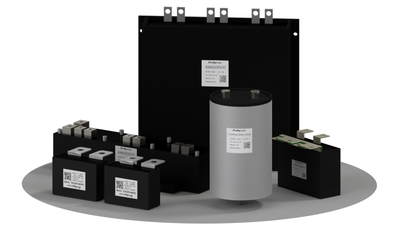
Power Film Capacitors
We have a lineup of custom-made film capacitors for power applications that require high capacitance and high current, such as industrial equipment and automotive applications.
Series List
Film Capacitors
| Type | Series | Details | Search | Features | General purpose | Miniaturized | High Ripple | heat-resistant | High Voltage | AC Rated voltage | CR-Network | Rated voltage(V) | Capacitance(μF) | Category Temperature Range | Series |
|---|---|---|---|---|---|---|---|---|---|---|---|---|---|---|---|
| Metallized Polypropylene Film Capacitors | MPB ※1 |
|
|
Standard |
◯ | DC250~630 | 0.01~4.7 | -40~+105℃ | MPB ※1 | ||||||
| MPK ※1 |
|
|
Miniaturized |
◯ | DC450~800 | 0.1~4.7 | -40~+105℃ (+85℃) | MPK ※1 | |||||||
| MPE ※1 |
|
|
High Voltage |
◯ | DC800~1,600 AC250~700 |
0.001~0.56 | -40~+105℃ | MPE ※1 | |||||||
| MPH ※1 |
|
|
High Current |
◯ | DC100~800 | 0.047~22 | -40~+105℃ | MPH ※1 | |||||||
| new MPY ※1 |
|
|
Miniaturized, |
◯ | ◯ | DC450 | 0.47~10 | -40~+105℃ | new MPY ※1 | ||||||
| new MPT ※1 |
|
|
High heat resistance |
◯ | ◯ | DC630 | 1~6.8 | -40~+125℃ | new MPT ※1 | ||||||
| MPN ※2 |
|
|
Ultra Miniaturized |
◯ | DC450~630 | 0.1~4.7 | -40~+85℃ | MPN ※2 | |||||||
| MPKA ※1 |
|
|
Across-the-line, |
◯ | ◯ | AC125~275 | 0.01~1 | -40~+85℃ | MPKA ※1 | ||||||
| PCK ※1 |
|
|
High Ripple Current, |
◯ | ◯ | DC450~2,000 | 0.01~33 | -40~+105℃ (+85℃) | PCK ※1 | ||||||
| MPF ※1 |
|
|
Ultra High Voltage |
◯ | DC10,000~20,000 | 0.027~0.68 | -40~+85℃ | MPF ※1 | |||||||
| Metallized Polyester Film Capacitors | MMB ※1 |
|
|
Standard |
◯ | DC100~630 | 0.01~10 | -40~+105℃ (+85℃) | MMB ※1 | ||||||
| MMG ※1 |
|
|
Miniaturized |
◯ | DC250~630 | 0.056~10 | -40~+105℃ (+85℃) | MMG ※1 | |||||||
| MMBA ※1 |
|
|
Across-the-line |
◯ | ◯ | AC125~250 | 0.01~1 | -40~+85℃ | MMBA ※1 | ||||||
| CR-Surge absober | MCRA-DP ※1 |
|
|
CR-Surge absober |
◯ | ◯ | ◯ | AC125~250 | C: 0.033~0.1 R: 47~120Ω |
-25~+85℃ | MCRA-DP ※1 | ||||
| Power Film Capacitors | MPC ※1 |
|
|
High Ripple Current |
◯ | DC700~1,600 | 0.1~2.2 | -40~+85℃ | MPC ※1 | ||||||
| MPCA ※1 |
|
|
For AC line |
◯ | ◯ | AC220~500 | 1~100 | -25~+70℃ | MPCA ※1 | ||||||
| HVC ※1 |
|
|
Low ESL |
◯ | ◯ | DC250~800 | 50~800 | -40~+105℃ | HVC ※1 | ||||||
| MPX ※1 |
|
|
Stud Mounting |
◯ | DC1,100~1,300 | 200~1,600 | -20~+70℃ | MPX ※1 | |||||||
| Polyester Film Capacitors | F2D ※2 |
|
|
Standard |
◯ | DC50~200 | 0.00047~0.47 | -40~+105℃ | F2D ※2 | ||||||
| Polypropylene Film Capacitors | P2S ※2 |
|
|
Low D.F |
◯ | DC100~250 | 0.00022~0.1 | -25~+85℃ (+70℃) | P2S ※2 | ||||||
| Polyphenylene Sulfide Film Capacitors | H2D ※2 |
|
|
High heat resistance |
◯ | DC50~100 | 0.00047~0.47 | -55~+125℃ | H2D ※2 |
*1:Some values are scheduled to be discontinued. Please check the "Details" for each series.
*2:Products have been discontinued. Please avoid adopting for new projects.
Series Chart
Technical Note

Catalog
Product Specifications
3.Taping Specifications(196 KB)
Cautions for Proper Use
Environmental Information
FAQ
Please let me know the service life of film capacitor.
The film capacitor will never wear out or fail if it is used within the rated voltage range having been normally set up.
However, this does not apply to the cases when the voltage exceeding the rated voltage is applied on it and when it is used in the high temperature/high humidity environment. In such cases, it is necessary to examine the details as to the propriety of its use and service life under respective conditions.
How much current can flow through the film capacitor?
Please refer to the allowable current data for frequency.
However, this data refers to the sine wave current. The waveform in the equipment in actual use frequently contains a considerably many high harmonic components. Even in slightly excess of the allowable values given in said data, self-heating of capacitor may fall below the allowable values in many cases. Finally, it is recommended to check and confirm the self-heating at the actual equipment.
Why the is derating of high frequency voltage necessary?
The high frequency voltage is to be limited by the allowable current value for high frequency as mentioned above. However, this voltage refers strictly to the AC components. In case when DC voltage is overlapped on it, the peak voltage should never exceed the DC rated voltage.
Moreover, in case of the waveforms different from the sine wave, it is also necessary to check and confirm whether the following conditions are satisfied.
(1) Current conditions are satisfied (less than the allowable current).
(2) In case when the pulse rated voltage is specified, Up-p voltage is lower than the rated voltage.